Abstract
Everyone has wondered how to control the MR2
Power steering pump so that it is not a noisy power hog because its always
on full throttle. Designing some sort of motor controller or using
a small off-the-shelf controller would not work for me. One, Im
not that great of a designer of controllers (Ill leave this up to Otmar).
Second, a small off-the-shelf controller would not work on high voltage
systems. Plus, I would have to program some type of Micro or Basic
Stamp to get all the functions I want.
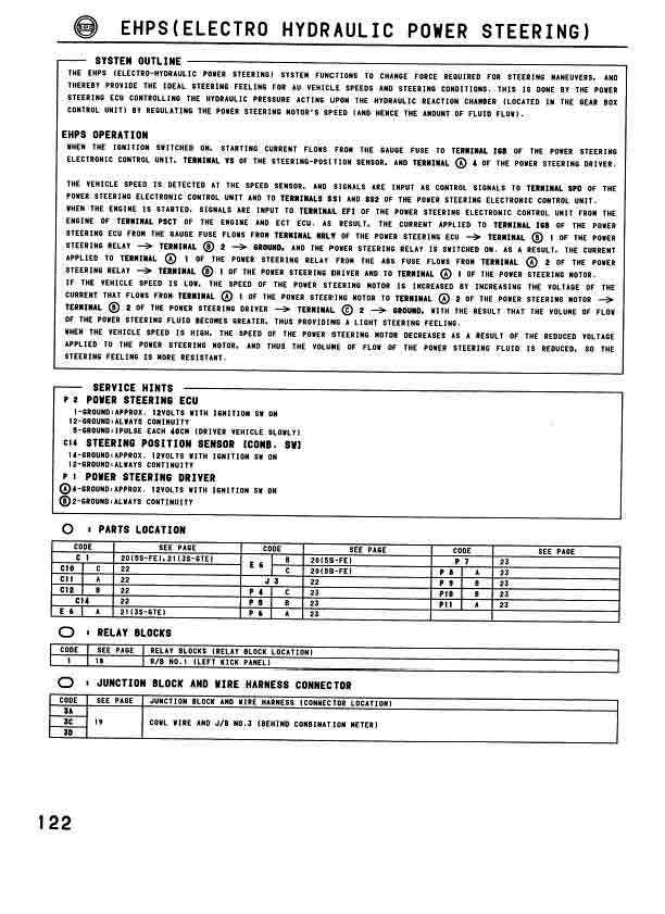
So I decided to get the original motor controller
from a MR2 at the junk yard and try to wire it up. Well, it works
better than I anticipated. One of the modes of the MR2 controller
is to slow the hydraulic pump to a stop when there is no movement of the
steering wheel or vehicle road speed: saves power! I have also wired
it to enable itself when the Zilla Contactor is engaged. I'm using
the original steering wheel sensor from the MR2, so it senses how much
steering I'm applying. It is also getting road speed info from the
cruise control speed sensor to limit over-steer at high road speeds.
It uses the sensors in the pump to tell you when the brushes are worn or
overheated.
What you need:
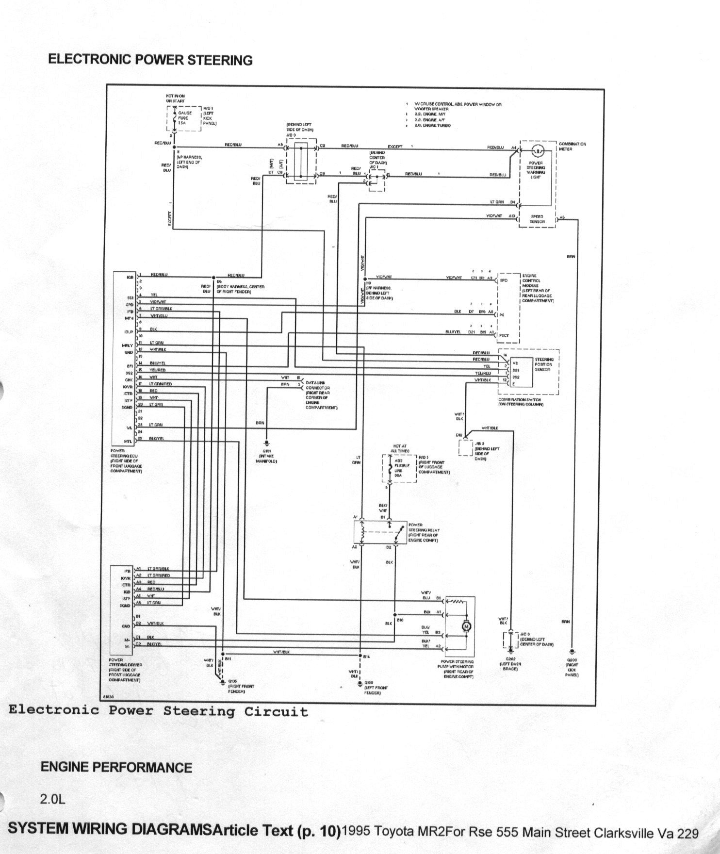
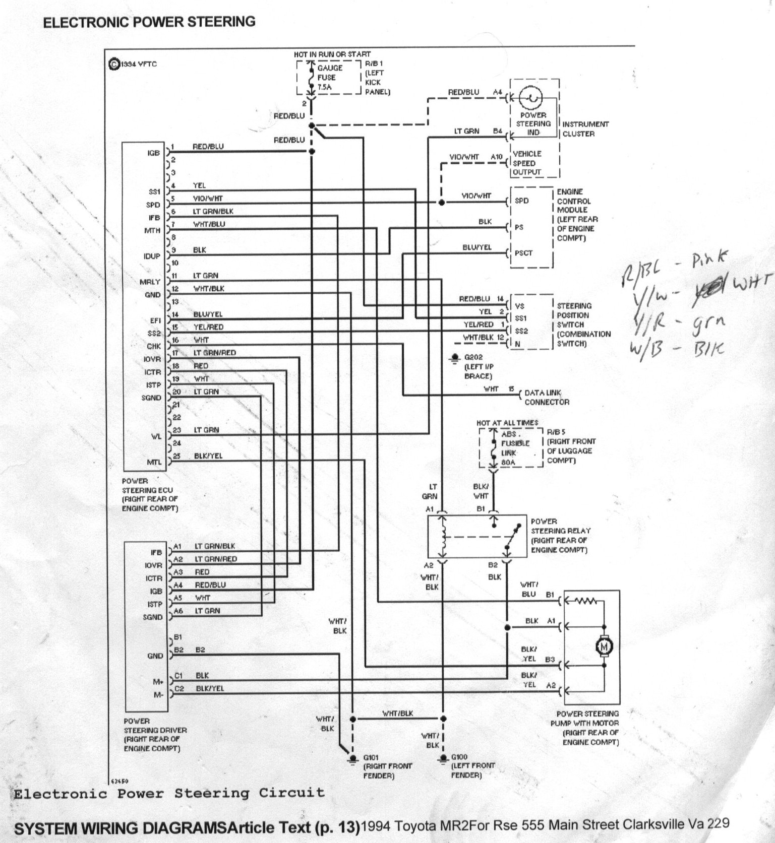
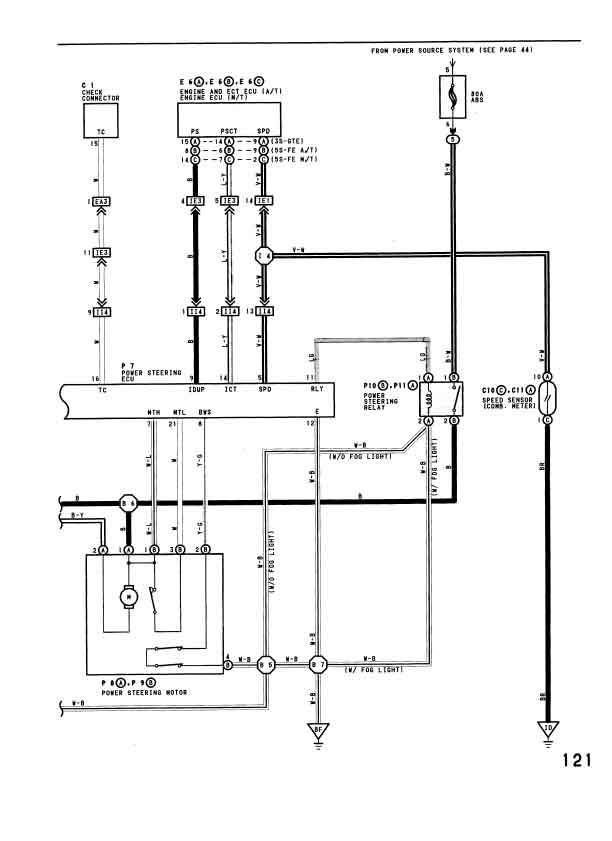
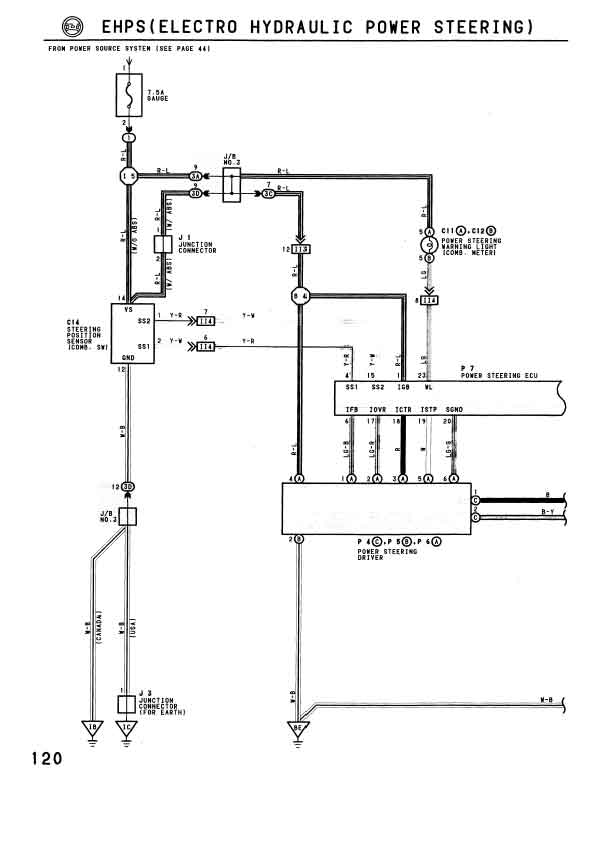
The P.S. schematics provided are from a 94
and 95 MR2, so try and get all the parts from a Toyota close as possible
to these years. There are a couple different versions of the schematics
here, so use the one that best suits your needs.
1. Hydraulic Pump from an MR2
2. P.S. ECU (not the main engine ECU)
3. P.S. Driver (Main Relay is externally attached)
4. P.S. Sensor (inside the switch cluster
from the steering column)
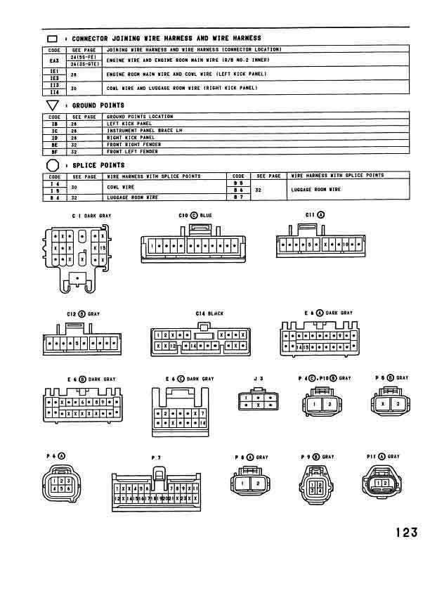
5. Wiring harnesses for all above
6. Micro-sized relay with N.C. contacts
7. 1K Ohm resister
8. Various multicolored automotive wire and
loom to rebuild the Harness.
9. 80 Amp Fuse
The Hook up:
With the schematics provided you have to build
a new wiring harness from the OEM harness cut out of the MR2.
Its a lot of work so get busy
Notes:
1. I used the original cruise control speed
sensor for my 85 S10 to drive the ECU and it has worked with good results.
Your results or pulse rates may vary.
2. The ICT (PSCT) is a control wire for the
main engine ECU to enable the P.S. when the engine is running. The
P.S. ECU is disabled when this wire is brought low (grounded). So
I used a micro-sized relay and a 1K Ohm resister to keep this wire low
until the main contactor is engaged. I hooked the small relay in
parallel with main contactor. My Zilla has no problem with this...
3. My Hydraulic pump was from a slightly different
year so it had only 3 sensor wires. After some testing I realized
that it was missing the V-L or Violet/Light Stripe wire. Look at
the schematic and you will see how easy this was fixed.
4. The TC (CHK) and IDUP wires I did not hook
up; apparently they are not needed.
Optional:
1. Put a switch in your dash to disable the
P.S. ECU via the ICT (PSCT) control wire. I call this Stealth Mode
2. I used a self-resetting 80 amp breaker
instead of a fuse. Your preference
Courtesy of John Grigg